Countershaft Sprocket
SAFETY FIRST: Protective gloves and eyewear are recommended at this point.
Removal
Left side upper and lower faring pieces. See the Side Fairings topic for more information.
The gearshift pedal must be removed. See the Gearshift Pedal topic for more information.
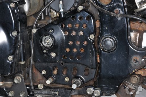


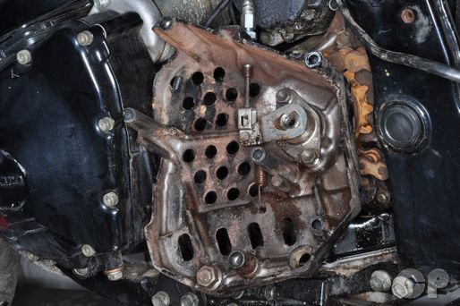
Remove the six countershaft sprocket cover bolts with a 5 mm Allen.
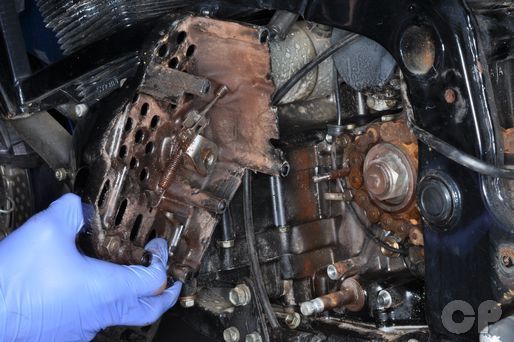
Remove the countershaft sprocket cover.


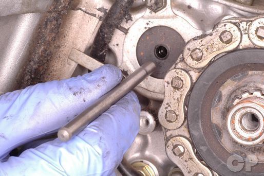
Remove the dowel pins from the crankcase.
To remove the clutch cable see the Clutch Cable Adjustment topic.
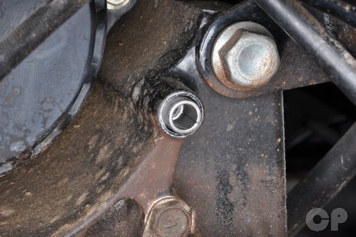
Remove the clutch cable push rod.
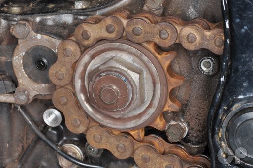


Loosen the countershaft sprocket bolt with a 10 mm socket. Remove the bolt and the washer. You can use the rear brake to hold the sprocket from turning if necessary.


Loosen the countershaft sprocket nut with a 32 mm socket. You can use the rear brake to hold the sprocket from turning if necessary.
Adjust the drive chain for maximum slack. See the Drive Chain Adjustment topic for more information.


Remove the outer damper holder and damper ring from the countershaft sprocket.
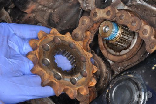
Slide of the countershaft sprocket.


Remove the inner damper ring and damper holder.
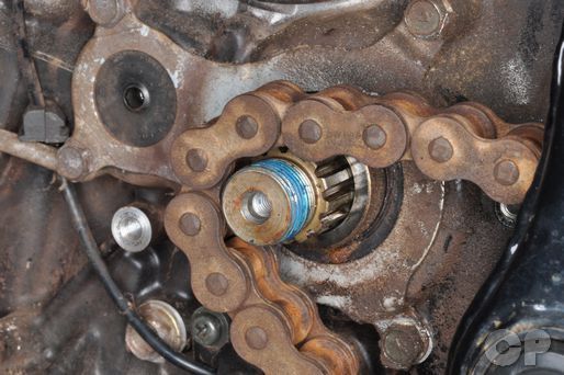
Set the drive chain on the end of the countershaft.
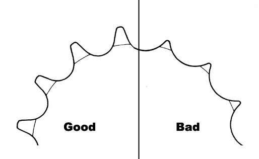
Inspect the sprocket for wear and damage.
Inspect the countershaft sprocket seal for damage and leaks.
Installation
Fit the inner damper holder and damper ring onto the countershaft.
Install the countershaft sprocket onto the countershaft. Engage the chain to the countershaft sprocket.
Install the damper ring and outer damper holder onto the countershaft sprocket.
Adjust the drive chain slack. See the Drive Chain Adjustment topic for more information.
Apply Blue Loctite to the threads on the end of the countershaft. nut on the countershaft. Torque the countershaft sprocket nut to specification with a 32 mm socket. You can use the rear brake to hold the sprocket from turning. Recheck the drive chain slack after tightening the nut.
(Countershaft Sprocket Nut Torque: 115 N-m or 83 lb-ft)
Coat the clutch push rod in Suzuki Super Grease "A." Install the clutch pushrod.
Suzuki Super Grease "A" - 99000-25030
Install the washer and bolt. Torque the bolt to specification with a 10 mm socket.
(Specification for Speed Sensor Rotor Bolt Torque: 8 - 12 N-m or 6 - 8.5 lb-ft)
Apply Suzuki Super Grease to the clutch release mechanism.
Suzuki Super Grease- 99000-25030
Install the countershaft sprocket cover dowel pins into the crankcase.
Set the countershaft sprocket cover in place. Make sure the clutch push rod fits into the release mechanism.
Install the six countershaft sprocket cover bolts and tighten them securely with a 5 mm Allen.
Install the gearshift pedal. See the Gearshift Pedal topic for more information.
Install the left side fairing pieces. See the Side Fairings topic for more information.
Copyright - Cyclepedia Press LLC

Note: If you are viewing this document offline be sure to visit the latest version online at http://www.cyclepedia.com before attempting any repairs. Updates are made without notice.